사실상 Game Engine 을 만들고 싶은건 아니다. Game Engine 을 사용한 어떠한 Product 를 만들고 싶었고, 그 Platform 이 Unreal Engine 이 됬든, Unity 가 됬든 사용하면 된다. 하지만 이미 상용화? 된 엔진들의 확실한 장점은 있지만, 그렇다고 해도, 너무 많은 방대한 정보를 이해하기에는 쉽지 않다. 예를 들어서, DirectX11 에서는 확실히 Low Level API 라고 하지만, 거의 High Level API 이다. 특히나 드라이버(인력사무소)가 거의 많은 작업들을 처리 해주었다. 그에 반대 되서, DirectX12 는 대부분의 작업을 따로 처리해줘야한다 (RootSignature, PipelineState, etc) 그리고 병렬 지원에 대해서도 충분히 이야기할수 있다. CommandList 를 병렬 처리가 가능하다고 한다. (이부분은 실제로 해보진 않았다.)
특히나, Commit 을 하기전에 Stream 방식인지, CommandList 에 일할것과, 일의 양을 명시해서 CommandQueue 에다가 넣어준다. 그리고 OMSetRenderTargets, IASetVertexBuffers 등으로 DX11 에서는 알아서 자동 상태 전이가 되지만, DX12 에서는 D3D12_RESOURCE_BARRIER 를 통해서 상태를 명시적으로 지정해주어야 할 필요가 있다. 이것 말고 등등 오늘은 DX12 의 어려움 또는 DX11 와 비교를 말을 할려는 목적은 아니다. 오늘은 나의 개발 로그를 공유하려고한다.
Motivation
예전부터 내가 직접 만들어보고 싶고, 표현해보고 싶었던게 있었고, 그걸 표현하기위해서, Game Engine 관련되서 Youtube 를 찾아보게 되다가 우연치 않게, Cherno 라는 Youtuber 를 보았다. 이 분은 EA 에서 일을 하다가 이제는 직접적으로 Game Engine Hazel 을 만들고 있다. 꼭 그리고 다른 Contents 도 상대적으로 퀄리티가 있다. 그리고 Walnut 에 보면 아주 좋은 Vulkan 과 Imgui 를 묶어놓은 Template Engine 이 있다. 꼭 추천한다. 그리고 개발하면서 다른 Resource 도 올려놓겠다.
Abstraction Layer
일단 나는 Multiplatform 을 Target 으로 Desktop Application 으로 정했다. 즉 Rendering 부분을 DX12 Backend 와 Vulkan Backend 로 나누어서, 추상화 단계를 거쳤다.
지금의 Project 의 구조를 설명하겠다. (전체적으로 HAL=Hardware Abstraction Layer 를 구상중)이며, 게임 엔진 내부에서 Platform 에 구애 받지 않게 설계 기준을 잡았다. 물론 추상화 계층은 삼각형 그리기 기준으로 일단 추상화를 작업을 진행하였다. 전체적으로 Resource 는 한번 추상화 작업을하고, IRenderBackend 로 부터 DirectX12 으로 할건지, Vulkan 으로 할건지 정의 하였다. 아직 작업할 일은 많지만, 한번에 하지 않으려고 진행중이다.
첫번째로, ImGUI 를 같이 사용하려면, ImGUI 용 descriptor heap 을 따로 만들어줘야한다. Example-DX12 Hook 여기에 보면, 아래 처럼 descriptor 를 만드는걸 확인 할수 있다. 그리고 내 DX12Backend 쪽에서도 이러한 방식으로 진행하고 있다.
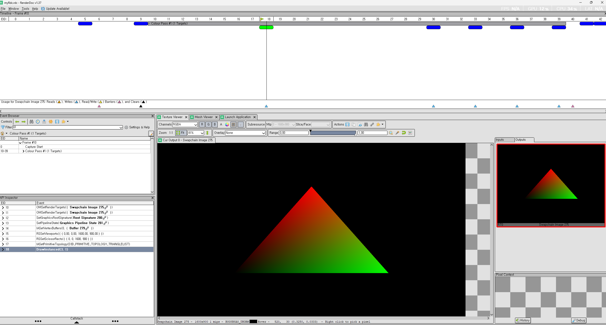
삼각형을 그리기만하는데, 삼각형이 그려지질 않는다. 그래서 이걸 RenderDoc 으로 체크를 해보겠다.
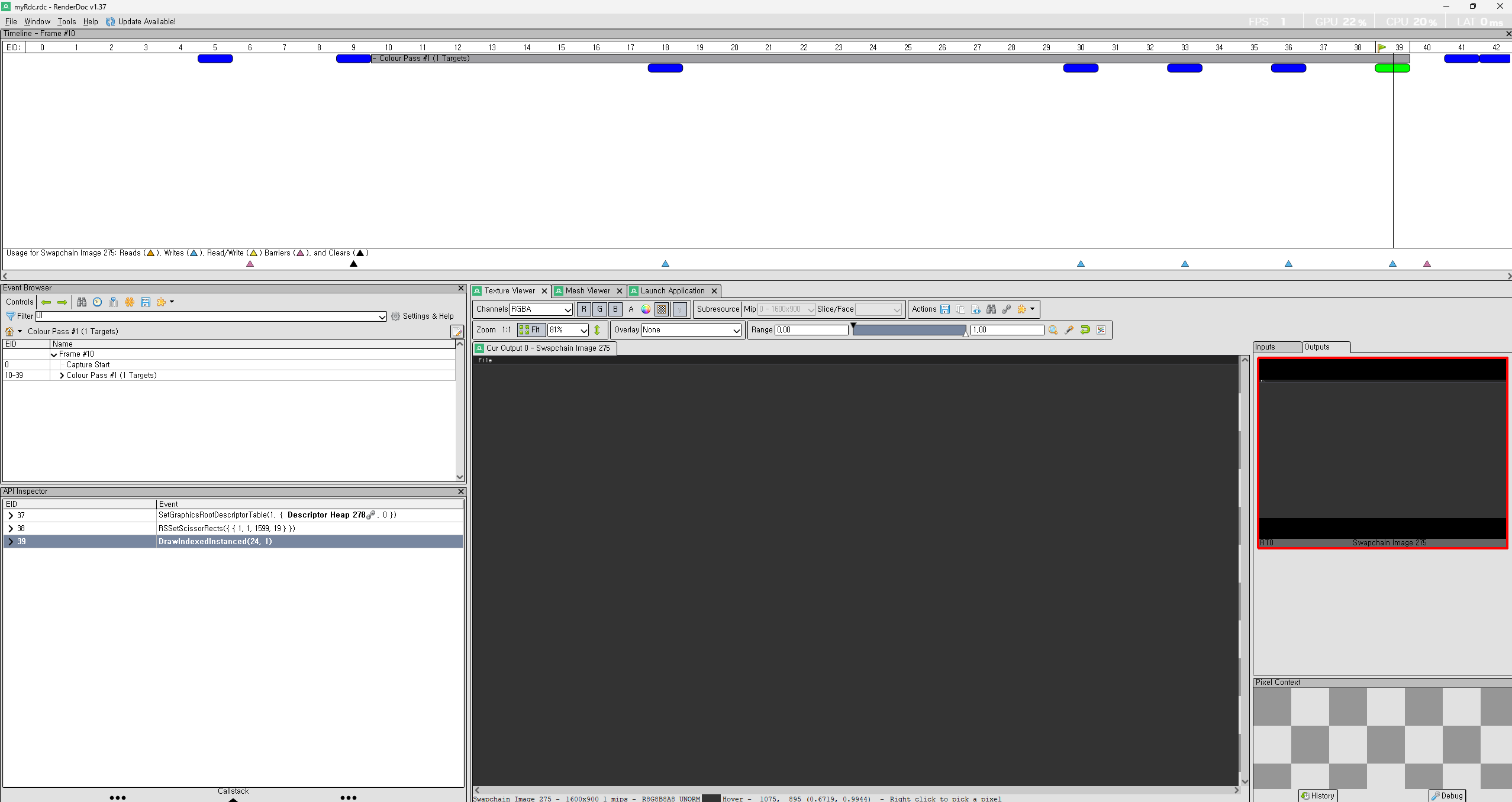
삼각형은 완벽하게 그려지고 있다. 하지만 그 다음 Pass 에 보면 없어진다.
이거에 대해서 찾아보다가, RenderTarget 에 둘다 그릴려구 해서 그렇고, 마지막에 Update 하는 부분이 ImGUI 에서 Docking 또는 Viewports Enable 을 했을시에 문제가 있다고 한다. 이럴떄, 기본적으로, ImGUI 에서는 GPU Rendering 상으로 기능을 독릭접인 자원을 활용하기 위해서 따로 만든다고 말을 하였다. 기본적으로 Viewports 를 Enable 했을시에, 새로운 Viewport 의 배경색은 Gray 색깔이라고 한다. 그래서 마지막에 Rendering 을 했을시에, Gray 로 덮어버린다. 즉 ImGUI 는 Texture 기반의 UI 요소를 그린다. (즉, ImGUI 의 내부 관리가 아닌 OS 창으로 Rendering 이 된다.)
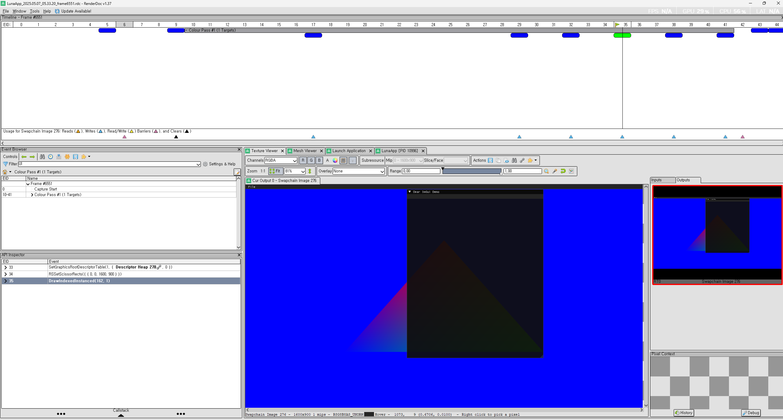
둘다 방법론은 같다. 그래서 아래와 같이 결과가 나왔다. 결국에는 해야하는 일은 하나의 RenderTarget 에 병합? (Aggregation) 이 맞는것 같다. 그리고 중요한건 RenderTarget 이 정확하게 ImGUI 와 삼각형 그리는게 맞는지 확인이 필요하다. 아래는 Aggregation 한 결과 이다.
Dependencies
모든 Dependency 는 PCH 에서 참조하고 있다. 참고로 vcpkg 는 premake 에서 아직 disable 하는걸 찾지 못했다. src/vendor 안에 모든 dependency 가 있다.
Rendering API Related
d3d12ma -> Direct3D Memory Allocation Library
dxheaders -> DirectX related headers
dxc -> HLSL compiler
volk -> Vulkan Loader
vulkan -> you need to download sdk from vulkan webpage
Series data refers to data where the state at one point in time is dependent on the states before (or after) it. Examples include input data for sentiment analysis, music analysis, or even large language models (LLMs). These tasks all rely on sequences of information—also known as time series data.
What is RNN
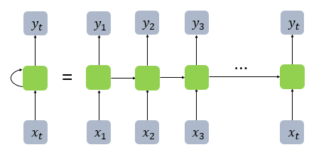
RNN, or Recurrent Neural Network, refers to a type of neural network where data is processed sequentially, one step at a time. This sequential nature allows RNNs to handle inputs such as words in a sentence, musical notes, or time-series sensor data.
The core building block of an RNN is the cell—a unit inside the hidden layer that performs activation and maintains memory. These are often referred to as memory cells, because they try to “remember” previous information in the sequence.
At each time step, the memory cell receives two inputs:
The current input (e.g., the current word or note)
The hidden state from the previous time step
This structure enables recursive reuse of hidden states across time, making the network capable of learning temporal dependencies.
One of the key components of RNNs is the hidden state. Each memory cell carries a hidden state, and at every time step, this hidden state is updated using both the current input and the previous hidden state. This allows the network to “remember” past context as it processes the sequence step-by-step.
When the RNN is unrolled in time, it forms a chain-like structure, where each cell is connected to the next, passing along the hidden state as shown in the diagram.
In RNNs, each hidden state at time t depends on the hidden state from the previous time step (t-1). This recursive structure allows the network to “recall” past information over time.
However, this also leads to a major issue:
As information is passed along through many time steps, older data tends to be lost. The longer the sequence, the harder it becomes for the model to retain information from earlier time steps.
In addition, as the depth of the unrolled RNN increases, the model suffers from the vanishing gradient problem during backpropagation—where gradients become too small to update earlier layers effectively.
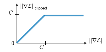
This makes it extremely difficult to learn long-term dependencies. One Common Solution to this problem is gradient clipping As shown in the diagram, a constant C is defined as a threshold. If the gradient exceeds this value, it is scaled back to prevent it from exploding or vanishing entirely.
This technique helps stabilize training, especially in deep RNNs or long sequence tasks.
LSTM & GRU
To address the issue of losing information from earlier time steps, a specialized architecture was introduced: LSTM (Long Short-Term Memory).
LSTM is designed to capture both short-term and long-term dependencies in sequential data, allowing the model to selectively retain or forget information over time.
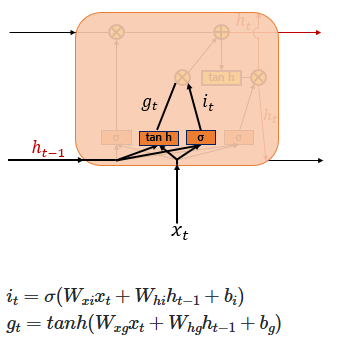
Although the above equations may look quite complex, they essentially involve multiple gates, each performing a specific role. Mathematically, the representation of these gates can be expressed as shown in the image below.
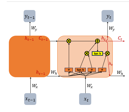
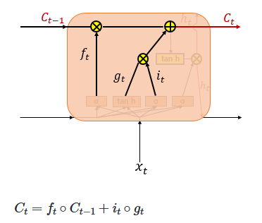
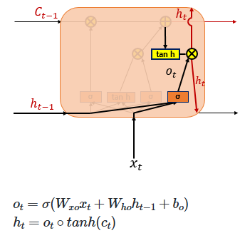
If we break down these equations further and represent them in a simplified diagram, the image below might help make the concept easier to understand.
As mentioned earlier, each gate has a specific role. Let’s examine them one by one from left to right:
1. Forget Gate (Decides Whether to Erase the Cell State or Not)
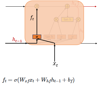
The Forget Gate is responsible for deleting unnecessary information. At the current time step 𝑡, the input 𝑥𝑡 and the previous hidden state ℎ𝑡 −1 are passed through a sigmoid function, producing values between 0 and 1. Values closer to 0 indicate that much of the information is discarded, while values closer to 1 mean the information is retained. This gating mechanism controls how the cell state is updated accordingly.
2. Input Gate
The Input Gate is used to process the new information to be added to the cell state. As shown on the right, the current input 𝑥𝑡 is multiplied by the weight matrix 𝑊𝑥𝑖, and the previous hidden state ℎ𝑡−1 is multiplied by 𝑊ℎ𝑖. Their sum is then passed through a sigmoid function. At the same time, the current input 𝑥𝑡 multiplied by 𝑊𝑥𝑔 and the previous hidden state ℎ𝑡−1 multiplied by 𝑊ℎ𝑔 are summed and passed through a hyperbolic tangent (tanh) function. The result of this operation is denoted as 𝑔𝑡
In other words, the combination of the sigmoid output (ranging from 0 to 1) and the tanh output (ranging from -1 to 1) determines how much new information is selected to update the cell state.
3. Cell Gate ***
In a standard RNN, only the hidden state is passed along to the next time step. However, in an LSTM, both the hidden state and the cell state are passed forward. The Forget Gate selectively removes some information from the cell state, while the element-wise product of the input gate activation 𝑖𝑡 and the candidate values 𝑔𝑡 determines how much new information is added.
These two components—the retained memory and the newly selected information—are then combined (summed) to update the current cell state 𝐶𝑡 This updated cell state is passed on to the next time step 𝑡+1. If the forget gate output 𝑓𝑡 is zero, the previous cell state 𝐶𝑡−1 is effectively reset to zero, meaning the cell only retains the newly selected information.
4. Output Gate & Hidden State
Finally, the Output Gate computes the output at the current time step 𝑡. It takes the current input 𝑥𝑡 and the hidden state, passes them through a sigmoid function to produce the output gate activation 𝑜𝑡. Meanwhile, the current cell state 𝐶𝑡 is passed through a hyperbolic tangent (tanh) function, producing values between −1 and 1. The element-wise product of these two values filters the cell state output, resulting in the new hidden state, which is then passed on to the next time step.
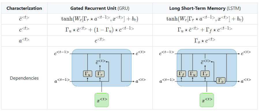
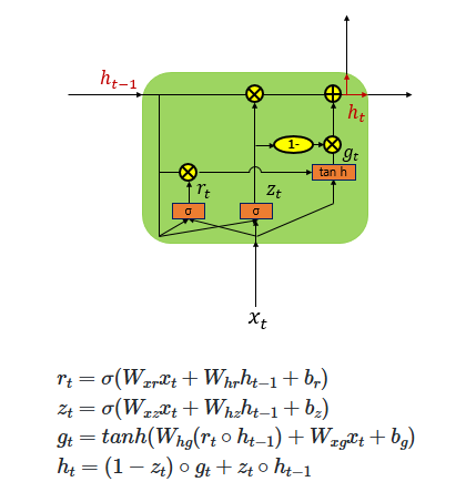
As shown in the diagram, the LSTM architecture divides these operations into multiple gates. In contrast, the GRU (Gated Recurrent Unit) simplifies this by combining some of these functions into just two gates: the Update Gate and the Reset Gate. This reduction results in a simpler structure while still effectively updating the hidden state over time, making the GRU a streamlined variant of the LSTM.
From Deep Learning Aspirations to Systems Development: My Unexpected Path into AI
During grad school, I studied Deep Learning, thinking it was a promising field worth diving into. I was genuinely excited about neural networks and how they were changing the landscape of tech.
But after graduation, I found myself doing something completely different—systems development. It felt disconnected from AI at first, and honestly, a bit frustrating. Still, I took it as a good opportunity and kept going. Surprisingly, that path led me back to AI—just from a different angle. I ended up working on systems that supported Computer Vision features. I wasn’t building models, but I was helping them run efficiently in real environments.
Why CNN?
At first, I tried training image data using a simple Multi-Layer Perceptron (MLP). To do that, I had to flatten the 2D image into a 1D vector. While this made it technically possible to train, it came at a cost—the model lost all the local and topological information in the image. It couldn’t understand where features were located, only what values existed. This made learning abstract concepts in images inefficient and slow.
To solve this, I turned to Convolutional Neural Networks (CNNs), which preserve spatial information using the concept of a receptive field—like how a lifeguard watches over a specific area of a pool, each convolutional filter focuses on a local region of the image.
Preliminary
In CNNs, we use small filters (or kernels) that slide over the image. Each kernel has weights (e.g., a 3×3 filter) and performs convolution operations followed by a bias addition and an activation function (like ReLU or Sigmoid). This produces a feature map that captures localized patterns in the image.
For example, filters like the Sobel operator are hand-designed to detect edges, but in CNNs, these filters are learned automatically during training. As a result, CNNs can effectively capture local features and build up abstract representations layer by layer.
By using convolutional layers instead of fully connected layers, the model not only gains efficiency but also becomes much better at recognizing patterns in images.
1. LeNet - Gradient Based Learning Applied to Document Recognition
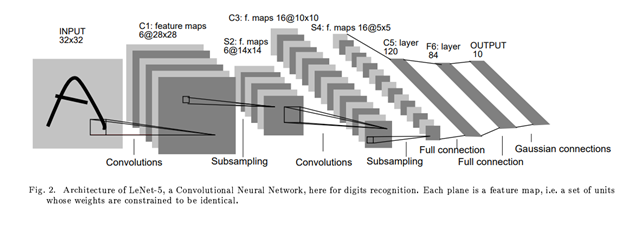
One of the earliest and most influential CNN-based architectures was LeNet, developed by Yann LeCun. It was originally designed for handwritten digit recognition (e.g., MNIST) and laid the groundwork for modern convolutional networks.
The input to LeNet is a 32×32×1 grayscale image. The first convolutional layer applies 6 filters of size n×n (typically 5×5), resulting in a feature map of size 28×28×6. This means each of the 6 filters scans the input image and extracts different local features.
After convolution, a subsampling (or downsampling) layer is applied—usually a type of average pooling—which reduces the spatial resolution. This pattern of Convolution → Subsampling repeats, gradually extracting higher-level features while reducing dimensionality.
Finally, the network flattens the feature maps and passes them through one or more fully connected layers, similar to an MLP, to perform classification.
2. AlexNet - ImageNet Classification with Deep Convolutional Neural Network
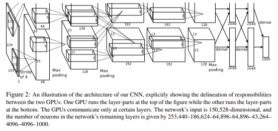
While traditional face detection algorithms like Haar Cascades could recognize faces fairly well—especially with properly preprocessed input—AlexNet took things to a whole new level. Designed to handle 224×224 RGB images, AlexNet leveraged the power of GPUs for parallel computation, which allowed it to scale deeper and wider than previous models.
One interesting feature of AlexNet was its split architecture: the network was divided into two parallel streams to take advantage of multi-GPU setups.
AlexNet also introduced several key innovations that became standard in deep learning:
ReLU Activation: Instead of using sigmoid or tanh, AlexNet used the ReLU function f(x) = max(0, x) for faster convergence and to mitigate the vanishing gradient problem.
Dropout: To combat overfitting, AlexNet randomly dropped units during training, forcing the network to learn redundant representations.
Overlapping Pooling: Unlike previous networks that used non-overlapping pooling (e.g., pooling window size = stride), AlexNet used 3×3 pooling windows with stride 2, allowing windows to overlap. This reduced the output size and helped capture more spatial detail, improving translational invariance.
Local Response Normalization (LRN): Since ReLU can produce very large activations, LRN was introduced to normalize the responses across adjacent neurons at the same spatial location. This helped prevent a few highly activated neurons from dominating.
Softmax: At the output, a softmax layer was used to convert logits into probabilities, amplifying confident predictions and suppressing weaker ones.
AlexNet’s success in the 2012 ImageNet competition marked a turning point for deep learning, showing that with enough data, compute, and smart design choices, neural networks could outperform traditional hand-engineered features by a large margin.
3. VGGNet - Very Deep Convolutional Networks for Large-Scale Image Recognition
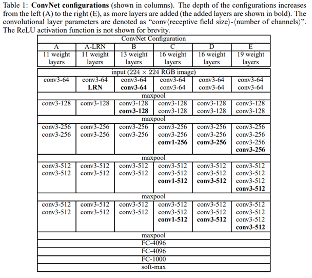
VGGNet built on the success of AlexNet, using similar input dimensions (e.g., 224×224×3), but introduced a key design shift: replacing larger filters (like 5×5) with multiple 3×3 convolutions stacked in sequence.
This approach brought several advantages:
Deeper architectures (16 or 19 layers) could be created without excessively increasing the number of parameters.
Multiple 3×3 filters in a row have the same receptive field as a larger filter (e.g., two 3×3 filters ≈ one 5×5), but with fewer parameters and lower computational cost.
As a result, VGGNet significantly improved performance while maintaining a clean, uniform architecture. Because of its regular structure and strong performance, VGGNet became a popular backbone network for tasks like semantic segmentation and object detection.
However, deeper networks introduced a new problem: during backpropagation, gradients could vanish as they moved backward through many layers, especially toward the input. This vanishing gradient problem made training very deep models difficult, eventually motivating the development of architectures like ResNet, which addressed this with residual connections.
4. GooLeNet - Going Deeper with Convolution
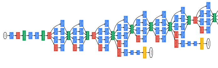
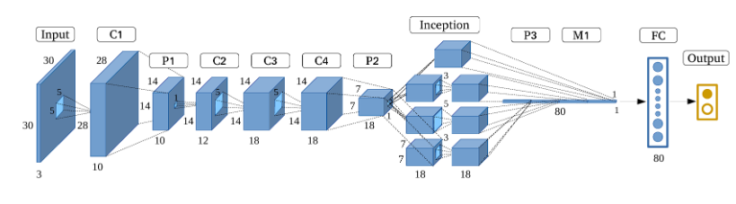
If VGGNet made networks deeper by stacking layers vertically, GoogLeNet (a.k.a. Inception v1) took a different approach—it went deeper in both width and depth (it goes deeper both vertically and horizontally).
GoogLeNet introduced the concept of the Inception Module, which allowed the network to process spatial information at multiple scales simultaneously. As the name suggests, this architecture digs deeper and deeper into the network structure.
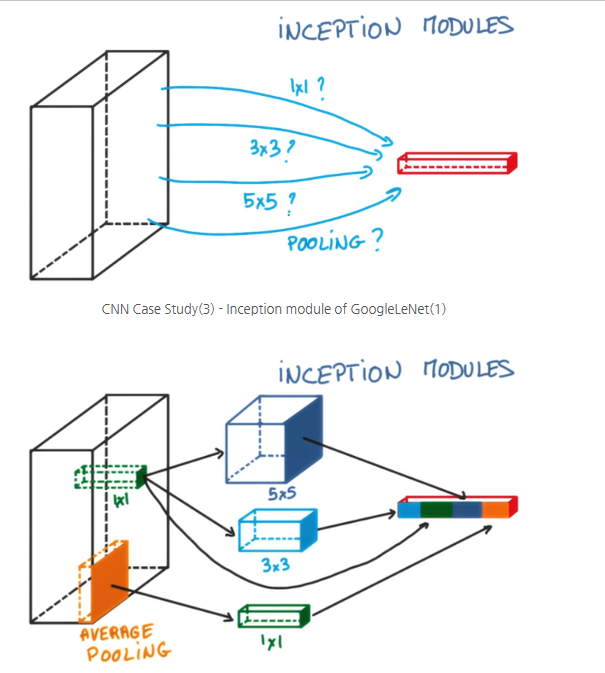
The unique part of GoogLeNet is the Inception Module. Take a look at the diagram below to understand it better.
As shown in the diagram above, one way to increase the depth of the network is by extracting feature maps using different kernels, then applying average pooling or max pooling, and finally concatenating the results.
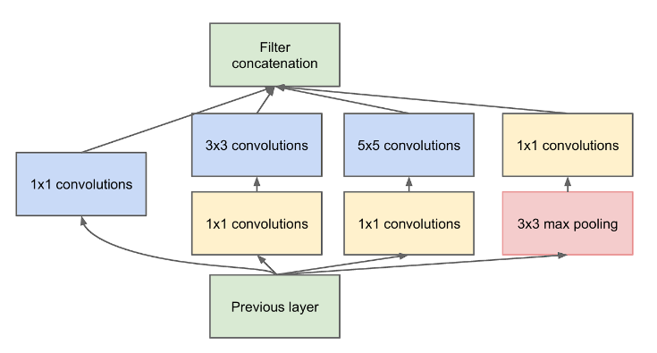
However, GoogLeNet went further and proposed a more efficient structure by combining multiple operations—like pooling and convolutions with different kernel sizes—in parallel. One of the key innovations was the use of 1×1 convolutions, either before or after other operations, forming what’s known as a bottleneck structure.
Using 1×1 convolutions significantly reduced the number of parameters and computation. For example, performing the same operation with 1×1 filters required only around 67,584 parameters (12,288 + 55,296)—a much smaller number compared to what would be needed without them.
Another interesting feature of GoogLeNet is the use of auxiliary classifiers. Instead of having a single softmax classifier at the end, it includes two additional softmax branches in the middle of the network. These auxiliary classifiers help mitigate the vanishing gradient problem by providing additional gradient signals during training.
Lastly, GoogLeNet replaces traditional fully connected layers with Global Average Pooling (GAP) near the end of the network. While the exact mechanism may seem abstract at first, the core idea is that GAP reduces each feature map to a single number by averaging spatial values, effectively summarizing global information without introducing additional parameters—unlike fully connected layers.
5. ResNet
Residual Learning: Tackling the Vanishing Gradient Problem. As mentioned in the previous post, one of the biggest issues with deep neural networks is the vanishing gradient problem. As networks get deeper, gradients calculated during backpropagation tend to shrink. The more layers you have, the more the gradients approach zero, which means the weight updates—especially in early layers—become negligible. In other words, the network struggles to learn because the influence of the output on earlier layers diminishes.
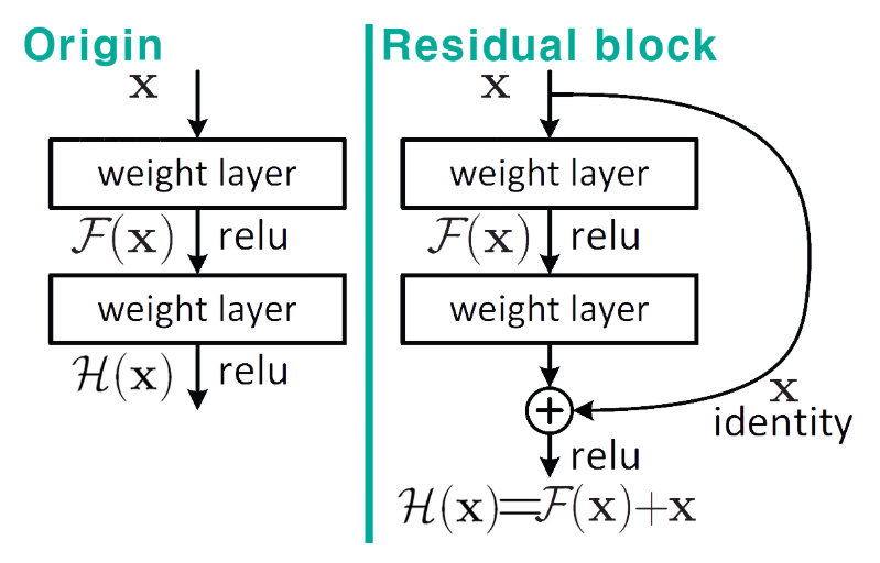
To address this, the concept of the Residual Block was introduced. It uses a mechanism called a skip connection, which forms the basis of residual learning. This allows the gradient to flow directly through the network, helping to mitigate the vanishing gradient issue even in very deep architectures.
Traditionally, the goal was to learn a function H(x) that maps the input x to the desired output y—in other words, to minimize H(x) – y. However, residual learning takes a different approach: instead of learning H(x) directly, the network learns the residual function, which is H(x) – x. The idea is that if the desired mapping is similar to the input, it’s easier to learn the difference between the input and output than the output itself.
By reformulating the learning objective this way, the model becomes easier to optimize and performs better in very deep configurations.
Why F(x) + x Helps: Stabilizing Gradients with Residual Blocks: The diagram above shows what we’ve been building toward: by using Residual Blocks, we compute F(x) + x, where F(x) is the output of a few convolutional layers and x is the original input. The key idea here is that when you differentiate this structure during backpropagation, the gradient always retains a value of 1 through the skip connection, ensuring that at least some portion of the signal survives as it flows backward.
Of course, this doesn’t completely eliminate the vanishing gradient problem, but according to the original paper, the issue was significantly mitigated by using Batch Normalization. Whether BatchNorm fully solves the vanishing gradient issue or just partially helps is still up for debate. One could argue it’s a major breakthrough—or just a minor contributor. Either way, it plays an important role in training very deep networks. BatchNorm’s role is to normalize the output of each layer, helping stabilize the gradient flow and speed up convergence.
As a result of stacking multiple residual blocks—50 to 152 layers deep—ResNet was able to achieve a depth 8× greater than VGGNet, while still being trainable.
This is how deeply layered networks with Residual Learning end up looking, as illustrated in the diagram below.
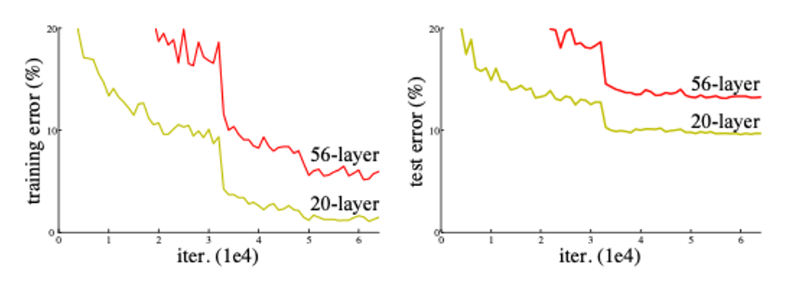
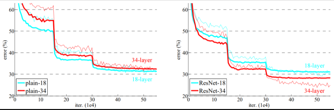
According to the paper, as the network depth increases, there is a noticeable trend in performance—but this trend is not necessarily due to overfitting.
Performance Analysis
Cause
Explanation
Resolution
Vanishing Gradient
Weakened gradients in upper layers during backpropagation
Skip Connection
Weight Attenuation
Imbalanced parameter updates in deeper layers
Residual Learning Architecture
Optimization Issues
Non-convex functions increase local minima
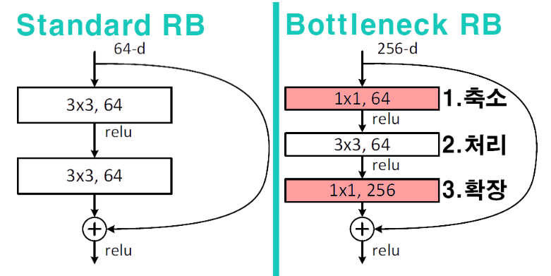
Bottleneck Architecture
The following diagram shows how these challenges have been addressed in the improved architecture.
Reduction stage: Reduce the number of parameters
Processing stage: Extract local features
Input/Output alignment: Match channel dimensions for 𝐻(𝑥) − 𝑥
6. DenseNet
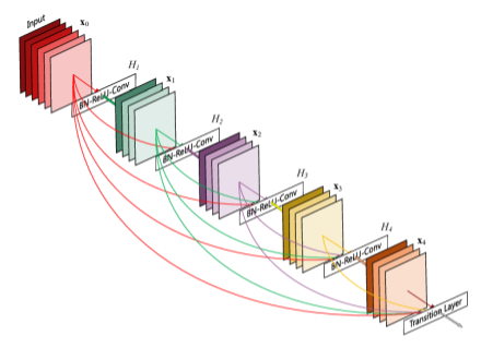
As shown above, the layers are densely connected, meaning each layer is connected to every other layer in a feed-forward fashion. This dense connectivity is the key point, and can be seen as an extension of residual learning.
Key characteristics include:
Feature reuse: Each layer receives the outputs of all preceding layers as its input.
Parameter efficiency: The number of feature maps is controlled by a growth rate (k), which limits how much the output grows per layer.
Implicit multi-scale learning: Low-level and high-level features are naturally fused through dense connections, enabling the network to learn across multiple scales automatically.
Component
Role
Mathematical Expression
Dense Block
Preserve feature map connections
xₗ = Hₗ([x₀, x₁, …, xₗ₋₁])
Transition Layer
Reduce dimensions and prevent redundancy
T(x) = Conv₁×₁(BN(ReLU(x)))
Bottleneck Layer
Improve computational efficiency
Hₗ = Conv₃×₃(Conv₁×₁(x))
From the equations above, we can clearly see the difference from ResNet. In ResNet, the residual connection is defined as: 𝑥𝑙 = 𝐻𝑙(𝑥𝑙 −1) + 𝑥𝑙 −1
This means each layer receives input only from the previous layer, and the outputs are summed. In contrast, DenseNet connects all preceding feature maps to the current layer as input, which increases the diversity of learned representations.
One drawback of ResNet is that if the two feature maps being summed come from different distributions, the addition operation may become less effective or even harmful.
In short:
ResNet uses sum
DenseNet uses concat
7. EfficientNet
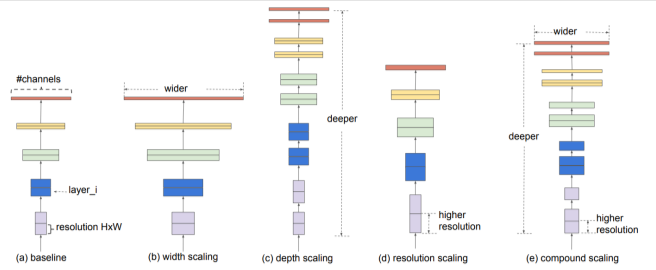
Traditional models typically scale along a single dimension—either depth, width, or resolution. What sets this approach apart is the idea of scaling all three dimensions in a balanced way. This is the core of what’s called Compound Scaling.
So the key point of this architecture lies in how to find the optimal balance between depth, width, and resolution.
Let’s briefly look at what each dimension represents:
Depth: Increasing the number of layers → allows the model to capture more complex patterns
Width: Increasing the number of channels → improves the model’s ability to learn fine-grained features
Resolution: Increasing the input image size → enables the use of higher-resolution spatial information
Based on these definitions, the architecture introduces a compound coefficient, denoted as ϕ (phi), to uniformly scale all three dimensions.
This coefficient is found using a greedy search, which led to the discovery of the following scaling constants: α=1.2 (depth) β=1.1 (width) 𝛾 =1.15 (resolution).
These constants are then used to guide the compound scaling process in EfficientNet | Component | Technique | Mathematical Expression | |——————-|———————————-|———————————————————————-| | MBConv | Inverted residual block | F̂(x) = T_proj(T_expand(x)) ⊙ SE(T_dw(x)) | | SE Block | Channel-wise attention modulation| w_c = σ(W₂ δ(W₁ · GAP(x))) | | Swish Activation | Smooth activation function | swish(x) = x · σ(βx)
6. MobileNet
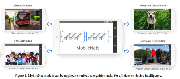
Just from the name alone, it’s clear where this model is meant to be used—on mobile devices. It’s a deep learning model designed specifically for mobile and resource-constrained environments.At its core, the key challenge was: “How can we reduce the amount of computation?” and that’s exactly what this architecture set out to solve.
In MobileNet, the goal is to balance latency and accuracy. Ultimately, the model achieves successful lightweight optimization, making it suitable for mobile and embedded devices.
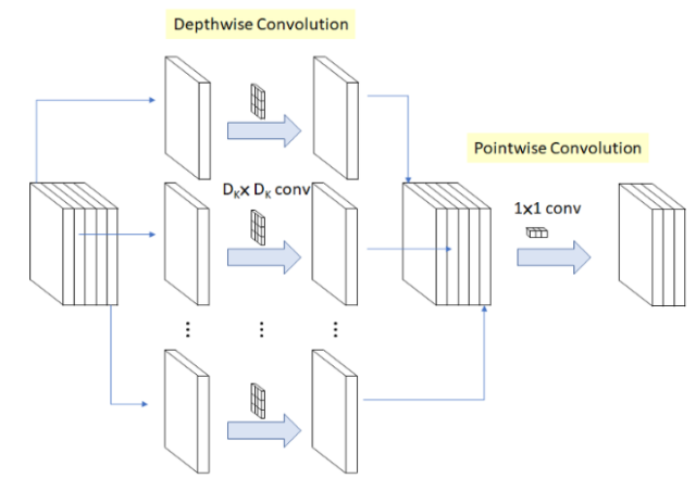
To understand how this is done, it’s important to grasp the concept of Depthwise Separable Convolution.
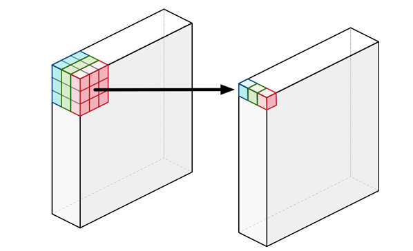
Unlike standard convolutions (often referred to as pointwise convolutions when using 1×1 kernels), depthwise separable convolutions learn a separate filter for each input channel. In traditional convolutions, each filter operates across all input channels, making it difficult to isolate spatial features. Depthwise convolution, on the other hand, performs a convolution independently per channel, similar to grouping filters—a technique that dramatically reduces computation while retaining performance.
Technique
Description
Channel Reduction
Reduce the number of channels using a width multiplier: channels × α (e.g., α = 1.0, 0.75, 0.5)
Compression
Reduce model size and parameters by setting a smaller α (e.g., α = 0.5)
Evenly Spaced Downsampling
Use stride = 2 in early layers (e.g., 224×224 → 112×112)
Shuffle Operation
Shuffle channels to promote cross-group information flow (e.g., ShuffleNet)
Knowledge Distillation & Compression
Model compression techniques like pruning, quantization, and distillation
Previous Post 글에서 봤듯이, Addition 을 Block 하나를 여러개의 Threads 들을 사용해서, Vector Addition 을 할수있다. 만약에 그럼 여러개의 Block 을 쪼개서 총 8 개의 사이즈를 가지고 있는 Array 를 더하려면 어떻게 하냐? 라고 물어볼수 있다 생각보다 간단하다. Block 두개를 사용해서, Thread 4 개씩 할당할수 있다. 아래의 코드 Segments 를 봐보자. 아래처럼 Block 2 개, thread 개수 4 개 이런 방식으로 구현을 하면 된다. 우리가 궁금한거는 결국 이 덧셈이 어떻게 되는지가 궁금한 포인트이다. 그러기 때문에 아래처럼 속도가 느려지더라도, printf 를 통해서, 볼수 있다. int i = blockDim.x * blockIdx.x + threadIdx.x 라고 써져있다. blockIdx.x 하고 threadIdx 는 대충 이해가 갈것이다. 하지만 BlockDim 은 뭔가라고 한번쯤 고민이 필요하다.
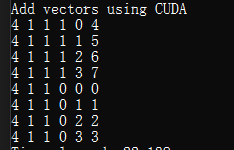
일단 위의 코드를 Printf 한 결과값을 한번 봐보자. 아래의 결과값을 보자면, Thread Block 은 4 x 1 x 1 이다. 그말은 Thread 의 개수 하나의 Block 당 4 개의 Thread 를 의미한다. 그리고, Block Index 는 총 2 개의 Block 을 사용하니 0, 1 로 나오며, 이제 ThreadIdx 는 그대로 나온다. 하지만 여기서 중요한건 바로 1 부터 돌아갔다는 소리이다. Multithreading 을 하다 보면 순서에 상관없이 돌기 때문에 그 환경 때문에 먼저 실행되는건 일이 끝난 순서대로 되서 순서와 상관없이 Operation 만 끝내면 된다는 방식에서 온거이다. 그리고 i 의 계산의 결과 값들을 봐도 우리가 예상하지 못한 결과를 볼수 있다.
결국에는 그럼 우리가 어떻게 Debugging 하지? 라는 질문이 있다.. 어찌저찌 됬든간에, CUDA 안에 있는 Thread Block Index, Thread Index, Block Dimension 같은 경우를 봐야하지 않을까? 라는게 포인트이다. Nsight 를 쓰면 굉장히 잘나와있다. 아래의 그림을 보면, 굉장히 Visualization 이 생각보다 잘되어있다. 안에 있는 내부 구성요소는 거의 위와 구현한 부분을 매칭하면서 보면 좋을것 같다.
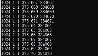
아래의 코드 같은 경우 대용량의 Data 처리를 위한 예제 코드라고 볼수 있다. 64 같은 경우는 내 컴퓨터 스펙중에 Maximum Threads Per Dimension 안에 있는 내용을 인용했다. 물론 이때는 Printf 를 쓰면 과부하가 걸릴수도 있으니 결과값만 확인하자. 물론 아래의 그림같이 Printf 를 한경우도 볼수 있다.
마침 Closure => Functor (Lambda Expression), Capture 이 부분이 생각보다 까다롭지 않을까? 싶었는데, 완전 C++ Syntax 가 똑같다. 단지 어떤 타입에 따라서 복사를 하는가에 따라서 다르다. (ex: C++ 에서 는 & (reference) 로 보낼지, 그냥 복사 Capture로 부를지를 [] or [&] 이런식으로 사용할수 있다, 하지만 swift 에서는 struct 는 value type 이므로 => 복사, class 처럼 reference type 이면, 주솟값을 넣어주는 형태)
Escaping Closure
이 부분을 이해하기위해서는 함수의 끝남! 을 잘 알아야한다. 예를 들어서 어떤 함수에서, closure() 가 바로 실행된다고 한다고 하자. 우리가 기대하고 있는거는 함수가 실행되고, closure 가 실행되는 방식으로 한다고 하자. 그러면 잘 작동이 될거다. 하지만 만약 비동기 처리가 이루어진다면 어떻게 되는걸까? 함수안에 내부 closure 는 실행이 될때까지 기다리고 있지만, 이미 그함수는 끝난 상태가 되버릴수있다. 그러면, 함수 내부에서 비동기 처리가 되는거가 아닌, 어떤곳에서 (ex: main) 에서 비동기 처리가 될거다. 그러면 빠져나가지도 못하는 상황이 되버린다. 이걸 방지할수 있는방법이 바로 @escaping 이라고 보면 된다. 기본적으로 closure 는 non-escaping 이다.
아래의 코드를 봐보자, 3 초 이후에 DispatchQueue 에서 비동기를 실시를 할건데, 이때 바로 들어가야하는게 @escaping keyword 이다. 즉 어떤 함수의 흐름에서, closure 가 stuc 한 부분을 풀어줘야 closure 의 끝맺음이 확실하다는것이다. (물론 함수 주기는 끝나게 된다.) 참고로 @Sendable Keyword 를 안쓴다면 Error 를 표출할것이다. 그 이유중에 하나는 일단 compleition (closure type) 은 referance type 이며, 이것을 비동기처리내에서 사용하려면, Thread Safe 라는걸 보장을 해야하는데, compiler 에서는 모른다. 그래서 명시적으로 Type 을 지정해줘야한다.
그리고 closure 측면에서는, 파라미터로 받은 클로저는 변수나 상수에 대입할수 없다. (이건 알아야 하는 지식중에 하나다, 가끔씩 compiler error 가 안날수도 있다.) 중첩 함수 내부에서, 클로저를 사용할 경우, 중첩함수를 return 할수 없다. 즉 함수의 어떤 흐름이 있다고 하면, 종료되기 전에 무조건 실행 되어야 한다는것이다. 근데 또 특이 한점 하나가 있다. 아래의 코드를 잠깐 봐보자.
자 거시적으로 봤을때는 closure 에 return 값을 기대할수도 있고, 없을수도 있다. 그걸 Optional(?) type 을 사용했다. Optional 을 사용한다고 하면, optional type argument 이기때문에 이미 escaping 처리가 될것이다. 라고 말한다. 즉 closure type 이 더이상 아니다. 그래서 자동적으로 escaping 한다고 보면 될것 같다.
Capture Ref & Caputer Value
이게 해깔릴수 있으니 정리를 해보자 한다. 일단 바로 코드 부터 보는게 좋을것 같다. 일단 Value Type 인 Struct 를 사용해서 구현을 해본다고 하자. 일단 Struct 가 Type 이 Value Type 이니까? 당연히 Capture 을 하면, 당연히 복사가 이뤄지기때문에 값이 안바뀐다고 생각은 할수 있다. 하지만, closure capture 자체가 기본이 변수의 메모리값을 참조 하기 때문에, person.age 의 주솟값을 reference 로 받기때문에 closure capture 가 reference 형태로 되는것이다. 그 아래의 것은 copy 다. 이건 capture 할 list 를 넘겨주는데, 이건 closure 가 생성하는 시점의 값을 하나 강하게 들고 있다고 볼수 있다. (즉 capture 한 값을 가지고 있다는것) 그러기때문에 capture list 를 사용할때는, 값으로 들어가기때문에 변경되지 않는다. 참고로 weak 를 사용하게 된다면, compiler 에서는 class 또는 class-bound protocol-types 라고 말할것이다. 즉 reference 타입일 경우에만 사용 가능 하다.
만약 multi-core CPU’s 또는 Parallel Execution 을 한다고 가정을 하면 어떨까? 즉 코어가 2개라면, 짝수개씩 병렬로 처리가 가능하다.
at time 0: CPU = core#0 = executes add_kernel(0, ...)
at time 0: CPU = core#1 = executes add_kernel(1, ...)
at time 1: CPU = core#0 = executes add_kernel(2, ...)
at time 1: CPU = core#1 = executes add_kernel(3, ...)
...
at time(n-1)/2: CPU = core#1 = executes add_kernel(SIZE - 1, ...)
그렇다면 GPU 는 어떻게 될까? GPU 는 엄청 많은 Core 들을 가지고 있기 때문에, 엄청난 Parallelism 을 가지고 갈수 있다. 아래와 같이 Time 0: 에 ForLoop 을 처리를 병렬 처리로 할수 있다는거다.
at time 0: CPU = core#0 = executes add_kernel(0, ...)
at time 0: CPU = core#1 = executes add_kernel(1, ...)
at time 0: CPU = core#2 = executes add_kernel(2, ...)
at time 0: CPU = core#3 = executes add_kernel(3, ...)
...
at time 0: CPU = core(#n-1) = executes add_kernel(SIZE - 1, ...)
위의 내용을 정리 하자면 아래와 같다. 즉 시간 순서별로 처리를 하는쪽은 CPU, 코어별로 처리를 하는건 GPU 라고 볼수 있다.
CPU Kernels
GPU Kernels
with a single CPU Core, For loop
a set of GPU Cores
sequential execution
parallel execution
for-loop
kernel lanuch
CPU[0] for time 0
GPU[0] for core #0
CPU[1] for time 1
GPU[1] for core #1
CPU[n-1] for time n-1
GPU[n-1] for core #n-1
CUDA vector addition 같은 경우 여러가지 Step 이 있다고 한다.
host-side
make A, B with source data
prepare C for the result
data copy host -> device
cudaMemcpy from host to device
addition in CUDA
kernel launch for CUDA device
result will be stored in device (VRAM)
data copy device -> host
cudaMemcpy from device to host
host-side
cout
Function Call vs Kernel Launch
기본적으로 C/C++ CPU 에서는 Function 을 부를때, Function Call 이라고 한다, 이의 Syntax 는 아래와같다.
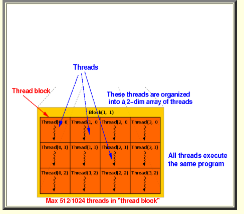
하지만 GPU 에서는 많이 다르다. c++ 에서 사용했을때와 다른 방식으로 Kernel(function) 을 사용한다. 이 Syntax 같 경우 Kernel launch Syntax 라고 한다. 의미적으로는 1 세트에 SIZE 만큼의 코어를 사용하겠다가 되는것이다. 또 다른 의미는 바로 1 이라는 인자 값은 Thread Block 몇개를 사용할건지와, 그 Thread Block 에 Thread 를 몇개 사용할지가 정의가된다. Thread Block 안에있는 Thread 는 코드 아래의 그림을 참조 하면 좋을것 같다.
실제로 예제 파일은 아래와같다. addKernel 이 실제로는 GPU 안에서의 FunctionCall 형태가 될거고, Index 를 넘기지 않기 때문에, 내부안에서 내 함수 Call 의 Index 를 찾을수 있다.
#include"cuda_runtime.h"
#include"device_launch_parameters.h"#include<stdio.h>__global__voidaddKernel(int*c,constint*a,constint*b){inti=threadIdx.x;printf("%d\n",i)c[i]=a[i]+b[i];}intmain(){constintarraySize=5;constinta[arraySize]={1,2,3,4,5};constintb[arraySize]={10,20,30,40,50};intc[arraySize]={0};// Add vectors in parallel.cudaError_tcudaStatus=addWithCuda(c,a,b,arraySize);if(cudaStatus!=cudaSuccess){fprintf(stderr,"addWithCuda failed!");return1;}printf("{1,2,3,4,5} + {10,20,30,40,50} = {%d,%d,%d,%d,%d}\n",c[0],c[1],c[2],c[3],c[4]);// cudaDeviceReset must be called before exiting in order for profiling and// tracing tools such as Nsight and Visual Profiler to show complete traces.cudaStatus=cudaDeviceReset();if(cudaStatus!=cudaSuccess){fprintf(stderr,"cudaDeviceReset failed!");return1;}return0;}cudaError_taddWithCuda(int*c,constint*a,constint*b,unsignedintsize){// ...int*dev_a=0;int*dev_b=0;int*dev_c=0;cudaError_tcudaStatus;// Launch a kernel on the GPU with one thread for each element.addKernel<<<1,size>>>(dev_c,dev_a,dev_b);//...// cudaDeviceSynchronize waits for the kernel to finish, and returnscudaError_tcudaStatus=cudaDeviceSynchronize();cudaStatus=cudaMemcpy(c,dev_c,size*sizeof(int),cudaMemcpyDeviceToHost);if(cudaStatus!=cudaSuccess){fprintf(stderr,"cudaMemcpy failed!");gotoError;}Error:cudaFree(dev_c)cudaFree(dev_a);cudaFree(dev_b);returncudaStatus;}
아래와 같이, cudaDeviceSynchronize() 는 kernel 이 끝날때까지 기다렸다가 Error_t 를 Return 을 하게 된다. 성공을 하면, cudaSuccess 를 받는다. 그리고 마지막으로는 CPU 쪽으로 복사를 해준는 구문 cudaMemcpy(...) 가 존재하고, Error 를 내뱉는곳으로 가게된다면, CudaFree 를 해준다.
물론, Host 쪽에서 계속 쭉 Status 를 사용해서, 기다리지만 Kernel 안에서, Kernel launch 중에도 에러가 발생할수 있다. 그 부분은 아래와 같이 받을수 있다. 원래는 cudaError_t err = cudaPeekAtLastError() 그리고 cudaError_t err = cudaGetLastError() 가 있다 둘의 하는 역활은 동일하다! 하지만 내부안에서 있는 Error Flag 를 Reset 을 해주는게 cudaGetLastError() 이며, cudaPeekAtLastError() 는 Reset 을 하지 않는다. 그말은 Reset 을 last error only 가 아니라 모든 Error 에 대해서 저장을 한다고 생각을 하면된다. 그리고 아래처럼 Macro 를 설정을 해주어도 좋다.
// Check for any errors launching the kernelcudaError_tcudaStatus=cudaGetLastError();if(cudaStatus!=cudaSuccess){fprintf(stderr,"addKernel launch failed: %s\n",cudaGetErrorString(cudaStatus));gotoError;}cudaError_terr=cudaPeekAtLastError();// CAUTION: we check CUDA error even in release mode// #if defined(NDEBUG)// #define CUDA_CHECK_ERROR() 0// #else#define CUDA_CHECK_ERROR() do { \
cudaError_t e = cudaGetLastError(); \
if (cudaSuccess != e) { \
printf("cuda failure \"%s\" at %s:%d\n", \
cudaGetErrorString(e), \
__FILE__, __LINE__); \
exit(1); \
} \
} while (0)
// #endif
근데 여기서 궁금증이 있을수 있다. 예를 들어서, c++ 에서는 Return 의 반환값을 지정할수 있었지만, Kernel 은 그렇지 못하다. 무조건 void 로 return 하게끔해야한다. 이건 병렬처리를 하기 때문에, 100 만개의 병렬처리를 한다면 100 만개의 return 값을 가지게 되는데 이건 error code 에 더 가깝다. 그러면 계산이 끝났다라는걸 명시적으로 어떻게 확인하느냐가 포인트일 일것 같다. 바로 Memory 를 던져줬을떄, 그 배열을 update 해서 GPU 에서 CPU 로 데이터가 Memcopy 가 됬을때만 확인이 가능하다.
예제 파일로 Vector 안에 모든 Element 에 +1 씩 붙이는 프로그램을 실행한다고 하면 아래와 같이 정의할수 있다.
#include"cuda_runtime.h"
#include"device_launch_parameters.h"#include<stdio.h>__global__voidadd_kernel(float*b,constfloat*a){inti=threadIdx.x;b[i]=a[i]+1.0f;}intmain(){constintarrSize=8;constfloata[arrSize]={0.,1.,2.,3.,4.,5.,6.,7.};floatb[arrSize]={0.,0.,0.,0.,0.,0.,0.,0.,};printf("a = {%f,%f,%f,%f,%f,%f,%f,%f\n",a[0],a[1],a[2],a[3],a[4],a[5],a[6],a[7]);float*dev_a=nullptr;float*dev_b=nullptr;cudaError_tcudaStatus;cudaMalloc((void**)&dev_a,arrSize*sizeof(float));cudaMalloc((void**)&dev_b,arrSize*sizeof(float));cudaMemcpy(dev_a,a,arrSize*sizeof(float),cudaMemcpyHostToDevice);add_kernel<<<1,arrSize>>>(dev_b,dev_a);cudaStatus=cudaPeekAtLastError();if(cudaStatus!=cudaSuccess){fprintf(stderr,"addKernel launch failed: %s\n",cudaGetErrorString(cudaStatus));}cudaStatus=cudaDeviceSynchronize();if(cudaStatus!=cudaSuccess){fprintf(stderr,"cudaDeviceSynchronize r eturned error code %d after launching addKernel!\n",cudaStatus);}// ResultcudaStatus=cudaMemcpy(b,dev_b,arrSize*sizeof(float),cudaMemcpyDeviceToHost);if(cudaStatus!=cudaSuccess){fprintf(stderr,"cudaMemcpy failed!");}printf("b = {%f,%f,%f,%f,%f,%f,%f,%f\n",b[0],b[1],b[2],b[3],b[4],b[5],b[6],b[7]);cudaFree(dev_a);cudaFree(dev_b);return0;}
그리고 참고적으로 꿀팁중에 하나는 const char* cudaGetErrorName( cudaError_t err) 이 함수가 있다.cudaError_t 를 넣어서 확인이 가능하며, Return 이 Enum Type 의 String 을 char arr 배열로 받을수 있으니 굉장히 좋은 debugging 꿀팁일수 있겠다. 또 다른건 const char* cudaGetErrorString(cudaError_t err) err code 에 대한 explanation string 값으로 return 을 하게끔 되어있다. 둘다 cout << <<endl; 사용 가능하다.
cudaGetLastError() -> Thread 단위 처리
여러가지의 Cuda Process 가 돌릴때, 내가 사용하고 있는 프로세스에서 여러가지의 Thread 가 갈라져서, 이들 thread 가 Cuda system 을 동시에 사용한다고 한다라면, CUDA Error 를 어떻게 처리하는지에 대한 고찰이 생길수도 있다. 그래서 각 Cpu Thread 가 Cuda 의 커널을 독자적으로 사용한다고 가정을 하면 Cuda eror 는 Cpu thread 기준으로 err 의 상태 관리를 하는게 좋다.
Given an array of non-negative integers numbers, and a target number target, write a function solution that returns the number of ways to add or subtract these numbers without changing their order to reach the target number.
For example, using the numbers ``, you can make the target number 3 in the following five ways:
Intially, when I try to solve this problem, I was thinking that this is typcial dp problem in such that if you select one number in the array, then you can choose either - number or positive number. Then, I was thinking you don’t really have to approach this problem with dp, just simple bfs or dfs can be possible
If we want to solve this by the recursive way, we need a constraint, constraint would be the vector’s size. Let’s say that we’ve started the +1 by adding the first number in the vector, then index has been already incremented by 1. So, by having the index, we can track what index we’ve used to get the target value.
Top-down Approach: This it pretty special one, one thing we need to notice is the way to save the totalsum with current sum. This is efficient way to store all possible sum. For example, if the total sum is 5, then -5 + 5 = 0 which is index at 0, -4 + 5 = 1(index), -3 + 5 = 2(index), and so on. This ensures the O(n * totalSum);
WOW, People are very ge, see if I understand correctly. The point here is to treat this problem as subset sum. I know the main goal is to find all possible solution to get to the target, but i think it’s good to break things up.
For example, if we have the list [1 -2, 3, 4], we set this as two sets one for +, the other for -. Then we can separate this s1 = [1, 3, 4] and s2 = [2]. Then, we can conclude that the totalSum = s1 + s2, but to find the target would be target = s1 - s2 (because we need to think all possible occurence of sum to be target). Then, we can write the equation like 2s1 = totalSum + target, then s1 = totalSum + target / 2. We call this as diff if this diff is not an integer, then we don’t have to compute.
Then, we can implement this idea. But this code doesn’t consider the sign changes, it’s either select one or not, which treat this as subset sum. (you should check any dp problem if you are curious because filling dp table is very similar to LCS or matrix multiplication)
intcache(intj,intsum,vector<int>&nums){if(j==0)returnsum==0?1:0;// doneif(dp[j][sum]!=-1)returndp[j][sum];intx=nums[j-1];intans=cache(j-1,sum,nums);if(sum>=x)ans+=cache(j-1,sum-x,nums);returndp[j][sum]=ans;}intfindTargetSumWays(vector<int>&nums,inttarget){constintn=nums.size();intsum=accumulate(nums.begin(),nums.end(),0);intdiff=sum-target;// Check if it's possible to achieve the targetif(diff<0||diff%2!=0)return0;diff/=2;vector<vector<int>>dp(n+1,vector<int>(diff+1,-1))returncache(n,diff,nums);}
classSolution{public:vector<int>findOrder(intnumCourses,vector<vector<int>>&prerequisites){intn=prerequisites.size();// same as numCoursesvector<int>inDegree(numCourses,0);vector<int>result;unordered_map<int,vector<int>>adj;for(inti=0;i<n;i++){adj[prerequisites[i][0]].push_back(prerequisites[i][1]);}// fill inDegreefor(autoit:adj){for(intnode:adj[it.first])inDegree[node]++;}queue<int>q;for(inti=0;i<numCourses;i++){if(inDegree[i]==0)q.push(i);}while(!q.empty()){intnode=q.front();q.pop();result.push_back(node);for(inte:adj[node]){inDegree[e]--;if(inDegree[e]==0)q.push(e);}}reverse(result.begin(),result.end());if(result.size()==numCourses){returnresult;}return{};}};
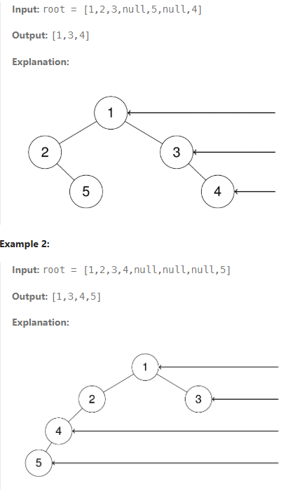
Given the root of a binary tree, imagine yourself standing on the right side of it, return the values of the nodes you can see ordered from top to bottom. The detail images are below:
Implementation
This is basically, we’re looking at the binary tree from right side. In the first example, the output would be [1,3,4]. In here, we can think that we can just traverse right side, but the next example shows that we can’t just look at the right traversal. nodes that are hide, show in the left root tree. So how do we approach to this problem. Since binary tree is part of complete binary tree, we can do level-order traversal.
The level traversal is basically below in c++.
vector<vector<int>>levelOrder(Node*root){if(root==nullptr)return{};// Create an empty queue for level order traversalqueue<Node*>q;vector<vector<int>>res;// Enqueue Rootq.push(root);intcurrLevel=0;while(!q.empty()){intlen=q.size();res.push_back({});for(inti=0;i<len;i++){// Add front of queue and remove it from queueNode*node=q.front();q.pop();res[currLevel].push_back(node->data);// Enqueue left childif(node->left!=nullptr)q.push(node->left);// Enqueue right childif(node->right!=nullptr)q.push(node->right);}currLevel++;}returnres;}
Then let’s solve it. let’s use deque instead because it’s efficient! What we want is we are going to use levelLength which it comes from the idea of complete tree. If the size is not equal to q.size() - 1, it’s the left view, and if it’s same it’s going to be right view.
/**
* Definition for a binary tree node.
* struct TreeNode {
* int val;
* TreeNode *left;
* TreeNode *right;
* TreeNode() : val(0), left(nullptr), right(nullptr) {}
* TreeNode(int x) : val(x), left(nullptr), right(nullptr) {}
* TreeNode(int x, TreeNode *left, TreeNode *right) : val(x), left(left), right(right) {}
* };
*/vector<int>rightSideView(TreeNode*root){vector<int>result;if(root==nullptr)returnresult;deque<TreeNode*>q;q.push_back(root);while(!q.empty()){intlvlLength=q.size();for(inti=0;i<lvlLength;i++){TreeNode*node=q.front();q.pop_front();// forces to get the right value if(i==lvlLength-1){result.push_back(node->val);}if(node->left!=nullptr){q.push_back(node->left);}if(node->right!=nullptr){q.push_back(node->right);}}}returnresult;}
There are a total of numCourses courses you have to take, labeled from 0 to numCourses - 1. You are given an array prerequisites where prerequisites[i] = [ai, bi] indicates that you must take course bi first if you want to take course ai. For example, the pair [0, 1], indicates that to take course 0 you have to first take course 1. Return true if you can finish all courses. Otherwise, return false.
Implementation
This problem resembles a typical graph problem, where detecting cycles is crucial. While DFS can be used with states like visited, not visited, and visiting, we’ll employ topological sorting via Khan’s algorithm instead. This choice is suitable for our needs because it efficiently orders nodes in a directed acyclic graph (DAG), which is relevant if we assume the graph doesn’t contain cycles.
Topological sorting relies on the indegree of nodes. Nodes with an indegree of 0, meaning they have no incoming edges, are always placed at the front of the queue. This is because they have no dependencies and can be processed immediately.
edges are pointed to 0 -> 1 (in order to take 0, we need to take 1)
what we need to prepare is the result vector, and the inDegree vector adjacent link list (link list can be just vector).
Then, we would have to everything we need. From prerequsites vector, we would need to push the course we need to take, then directed to prerequsite node(class). Then we increment inDegree vector. why are we increasing the inDegree vector, because we need to tell that there is edge points to 1 (in above example)
Then, we need to prepare for the queue, and check if the indegree is 0, which means it’s gonna be first to check. Then, we’re gonna check the outgoing edge from each node, and we are going to get rid of that edge (-=). Then, there is no incoming edge, then we push to the queue. Then we just have to check whether the size is equal or not to number of courses.